
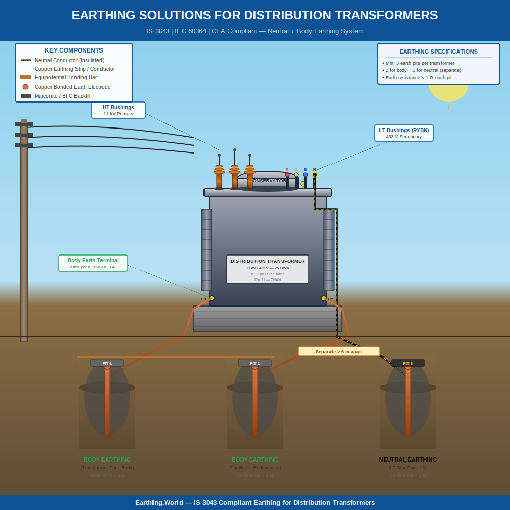
Earthing Solutions for Distribution Transformers — Engineered to IS:3043 & CEA Standards

Reliable earthing solutions for distribution transformers do far more than tick a compliance box. They protect crores worth of switchgear, keep single-phase voltages stable, and stand between a routine fault and a fatal accident. Yet across India, transformer grounding is still treated as a copy-paste activity — four pits, some salt, a bit of charcoal, and a hope that the soil cooperates. It does not. At Earthing.World, we design, engineer, and commission transformer earthing systems that are calculated from the soil up — site-specific, fault-current rated, and fully aligned with IS:3043:2018, CEA Regulations 2010, and global best practice.

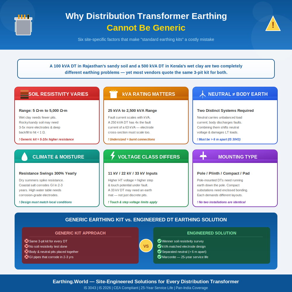
Why Distribution Transformer Earthing Cannot Be Generic

A distribution transformer sits at the most vulnerable junction in your power network — the point where high-voltage fault energy must be safely diverted to earth before it reaches loads, people, or sensitive equipment downstream. The earthing system at this junction has to do four jobs at once:

  • Carry the prospective fault current of the upstream HV network without thermal degradation.
  • Hold neutral potential close to true earth so that single-phase loads see balanced 230 V.
  • Operate protective devices fast enough to clear faults within prescribed time limits.
  • Survive 20–25 years of seasonal soil moisture changes, corrosion, and electromechanical stress.

No single template can satisfy all four objectives across the country’s wildly varied soil profiles — rocky Deccan plateau, sandy coastal belts, saline patches in Kutch, black cotton soil in central India, alluvial soil in the Indo-Gangetic plain. Each demands a separately engineered earthing design, not an off-the-shelf earthing kit.

Testimonial

What People Saying About Our Services

Submit Enquiry

Book an Appointment

Review an accurate quote within 3-5 days when you fill out the form on this page. Or, give us a call: (+91 72900 43400)

    How an Earthing.World Project Runs

    • Step 1 — Site Survey & Soil Resistivity Test. Our team visits the site, conducts a Wenner four-pin survey, photographs existing infrastructure, and notes lightning, drainage, and bonding context.
    • Step 2 — Earthing Design & Calculations. You receive a stamped design document covering grid layout, conductor sizing, electrode count, expected resistance, and bill of materials.
    • Step 3 — Material Supply. Copper-bonded rods, GI strips, Marconite (where specified), and all bonding hardware — supplied with batch-level test certificates.
    • Step 4 — Supervised Installation. Either turnkey installation by our crews or supervision of your contractor, with photo-documented quality checkpoints.
    • Step 5 — Commissioning & Handover. Fall-of-potential testing at the MET, signed test reports, and an as-built drawing package for your O&M file.
    Earthing.World

    The IS:3043 Misinterpretation That's Costing the Industry

    Since the original IS:3043 was published in 1987 (and updated in IS:3043:2018), the standard has clearly stated that all earthing connections in an installation must terminate at a single Main Earthing Terminal (MET). This is not an arbitrary rule — it ensures equipotential bonding, eliminates dangerous touch and step voltages, and provides a single reference plane for fault current dissipation.

    In practice, however, the clause has been widely misread as a requirement for separate, independent earth electrodes — typically two pits for the transformer body and two for the neutral, isolated from each other. The result is a fragmented earthing network where the body and neutral float at different potentials during a fault, defeating the very purpose of the system and creating elevated touch-voltage hazards near the transformer plinth.

    The correct interpretation, supported by Clause 27.1.2 of IS:3043:2018 and Rule 41 of the CEA (Measures Relating to Safety and Electric Supply) Regulations, 2010, is that all electrodes must be interlinked through the MET via a properly rated earth bus, with duplicate connections from the neutral and from the transformer enclosure. We design every system to that exact specification.

    What a Properly Engineered Transformer Earthing System Looks Like

    A correctly designed distribution transformer earthing system is the outcome of measurement, calculation, and material selection — in that order. Here is what each stage involves at Earthing.World:

    1. Soil Resistivity Survey (Wenner 4-Pin Method)

    Every project begins with a four-pin Wenner test taken at multiple electrode spacings to build a layered soil model. We never assume soil resistivity from a regional average — a 10 m shift can change resistivity by a factor of five in some terrains. The measured profile feeds directly into the earth grid calculation.

    2. Fault Current Capacity Sizing

    The conductors, electrodes, and bonding straps are sized using the prospective short-circuit current of the upstream network and the fault clearance time of the upstream protection. This is calculated using the Onderdonk / IEEE 80 thermal equation so that no component reaches its fusing temperature during the worst-case fault. Under-sized earth conductors are the single most common defect we find during third-party audits.

    3. Electrode Selection & Ground Enhancement Material

    Depending on soil conditions, we deploy copper-bonded rods, hot-dip galvanised pipe electrodes, or chemical-filled electrodes — backfilled with the right ground enhancement material. In high-resistivity terrain, we recommend Marconite conductive concrete (IEC 62561-7 compliant) over conventional bentonite. Marconite delivers a measured resistivity of approximately 0.1 Ω·m when set, holds that value for 25+ years without replenishment, and is corrosion-neutral — unlike chemical salts that leach into the surrounding soil and degrade the electrode.

    4. MET, Earth Bus & Equipotential Bonding

    All electrodes are interlinked through a copper or GI earth bus terminating at a clearly labelled Main Earthing Terminal. Duplicate, mechanically distinct connections are taken from the neutral bushing and from the transformer body. The MET is the single audit point for ground resistance verification and the single bonding point for surge protection, lightning protection, and any downstream LT panel earth bus.

    5. Verification — Fall-of-Potential Testing

    Before handover, ground resistance is verified by the 62 % fall-of-potential method at the MET, not at individual pits. Target values follow IS:3043 guidance:

    Installation Type

    Target Earth Resistance (IS:3043)

    Power station earthing

    ≤ 0.5 Ω

    EHT substation

    ≤ 1.0 Ω

    33 kV substation

    ≤ 2.0 Ω

    Distribution transformer structure

    ≤ 5.0 Ω

    Tower footing resistance

    ≤ 10.0 Ω


    Conventional Chemical Earthing vs. Engineered Earthing — A Side-by-Side

    Most procurement teams compare earthing vendors on the cost of a single pit. That comparison hides the real lifecycle cost. A pit that needs water and chemical top-ups every 18 months, and electrode replacement at year 5–7, is more expensive than a one-time Marconite-based installation that holds resistance for 25 years.

    Parameter

    Conventional Chemical Earthing

    Engineered Marconite System

    Resistivity of fill material

    ~3 Ω·m (Bentonite)

    ~0.1 Ω·m (set Marconite)

    Maintenance cycle

    Watering / chemical top-up every 12–18 months

    Zero scheduled maintenance

    Electrode life

    4–7 years (chemical corrosion)

    25+ years (corrosion-neutral)

    Performance in dry season

    Resistance rises sharply

    Stable across seasons

    Compliance with IS:3043 / CEA

    Depends on installer

    Designed and documented for audit

    10-year lifecycle cost

    High (recurring labour + material)

    Lower (one-time install)


    Who We Engineer Earthing Systems For

    Our transformer earthing solutions are deployed across India’s most safety-critical and uptime-sensitive sectors. Each environment imposes a different set of design constraints, and our engineering brief is shaped accordingly:

    • Hospitals and healthcare campuses — where touch-voltage limits at transformer plinths must protect non-electrical staff and where DG/transformer earthing supports life-critical loads.
    • Defence installations and strategic infrastructure — where redundancy, electromagnetic compatibility, and lightning protection bonding are mandatory.
    • Industrial plants and manufacturing units — where unplanned downtime from transformer trips translates directly to lost production.
    • Renewable energy parks and wind farms — where pad-mounted and pole-mounted distribution transformers face wide soil-resistivity variation across a single site.
    • Data centres and telecom switching centres — where ground resistance directly affects equipment ground reference and disturbance immunity.
    • Commercial real estate and high-rise developments — where DG-transformer-LT panel earthing must be coordinated under a single MET scheme.

    Why Earthing.World — Our EEAT Credentials

    Earthing is a discipline that punishes shortcuts and rewards engineering rigour. Here is what we bring to every project:

    • Experience: Over a decade of field-validated installations across hospitals, refineries, substations, wind farms, and high-rise commercial projects.
    • Expertise: In-house electrical engineers trained in IS:3043:2018, IEEE 80-2013, IEC 62305 (lightning protection), and IEC 62561-7 (earth enhancement materials).
    • Authoritativeness: Designs delivered with full calculation sheets, soil resistivity reports, fault current sizing, and as-built drawings — ready for electrical inspector audits.
    • Trustworthiness: Material certificates of conformity (IEC 62561-7 for Marconite), third-party fall-of-potential test reports, and warranty-backed performance commitments.

    Frequently Asked Questions – Transformer Earthing Solution

    What is the acceptable earthing resistance value for a distribution transformer in India?

    As per IS:3043:2018, the recommended earth resistance for a distribution transformer structure is 5 Ω or lower. In practice, for installations with sensitive downstream loads, we design for 1–2 Ω to provide a margin against seasonal soil resistivity variation.

    Do I need separate earth pits for the transformer body and neutral?

    You need duplicate, mechanically distinct connections from both the body and the neutral, as required by CEA Regulation 2010 and IS:3043. However, all electrodes should ultimately interlink at a Main Earthing Terminal — not float as independent islands. Treating the body earth and neutral earth as isolated systems creates dangerous potential differences during a fault.

    Is Marconite earthing better than chemical earthing for transformers?

    For most distribution transformer installations, yes. Marconite delivers a permanent low-resistance path (resistivity ~0.1 Ω·m once set), requires no watering or chemical replenishment, and has a service life of 25 years or more. Chemical earthing has a lower up-front cost but accumulates a higher 10-year lifecycle cost due to top-ups and electrode replacement.

    How often should transformer earthing be tested?

    Earth resistance should be measured at least once a year, and after every major fault event or electrical modification on site. Pre-monsoon and post-monsoon testing is recommended to capture seasonal extremes.

    Which standards govern transformer earthing in India?

    Primary standards are IS:3043:2018 (Code of Practice for Earthing), CEA (Measures Relating to Safety and Electric Supply) Regulations, 2010 — particularly Rules 41 and 42, and IEC 60364 for low-voltage installations. For lightning bonding, IEC 62305 applies. For ground enhancement materials, IEC 62561-7 is the reference.

    Can you retrofit our existing transformer earthing system?

    Yes. A large part of our work is corrective — auditing existing earthing, identifying compliance and performance gaps, and engineering a retrofit that brings the system to IS:3043 conformity without disrupting plant operations.