
Earthing Solutions for Factories — Engineered for Safety, Compliance & Uptime

An earthing system for a factory is not a wiring chore — it is a precision engineering deliverable. We have audited plants where a single mis-sized earth electrode pulled fault loop impedance high enough to defeat the RCCB on a 200 kW press, and we have seen PLC racks rebooting twice a shift because functional earthing was treated as an afterthought. Earthing solutions for factories have to do two jobs at once: route a fault current to ground fast enough to trip protection in milliseconds, and hold the equipment reference at a clean, stable potential so sensitive electronics, drives, and instrumentation keep running. Designs that ignore either half fail in service — usually expensively.

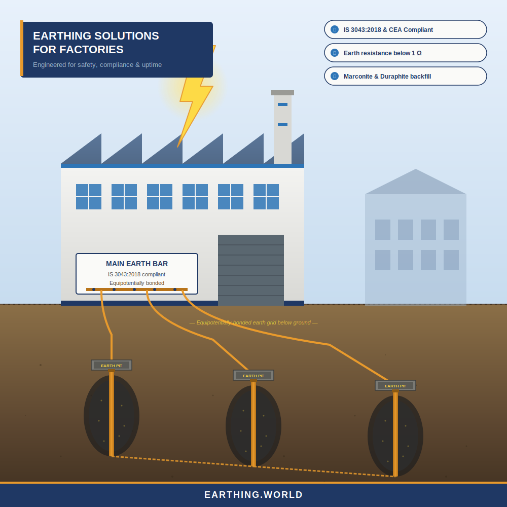
At Earthing.World, we design, supply, and commission industrial earthing systems that meet IS 3043:2018, IS 732, and the CEA (Measures relating to Safety and Electric Supply) Regulations, 2010. Every installation is engineered against measured soil resistivity, calculated touch and step voltage limits, and the actual fault current the plant can deliver — not a generic template.

Why Conventional Factory Earthing Keeps Failing

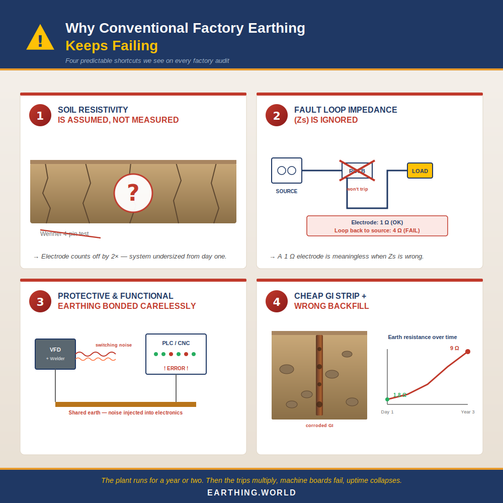
Most of the failures we see in industrial earthing systems trace back to four predictable shortcuts:

  • Soil resistivity is assumed instead of measured. A Wenner four-pin test takes a morning; skipping it produces electrode counts that are wrong by a factor of two.
  • The system is sized for steady-state earth resistance only, ignoring fault loop impedance (Zs). A 1 Ω electrode is meaningless if the loop back to the source is 4 Ω.
  • Protective and functional earthing are bonded carelessly, injecting switching noise from VFDs and welders straight into PLC and instrumentation ground references.
  • Cheap GI strip is buried with native soil backfill in rocky or sandy terrain. Resistance creeps up year on year and the system silently degrades until something burns.

The pattern is consistent across sectors — pharma, auto-ancillary, food processing, electronics assembly. The plant runs for a year or two, then leakage trips multiply, machine boards start failing, and the maintenance team is told “the earthing is bad” without anyone being able to say what specifically is bad. A proper factory earthing audit usually finds three or four compounding problems, not one.

Testimonial

What People Saying About Our Services

Submit Enquiry

Book an Appointment

Review an accurate quote within 3-5 days when you fill out the form on this page. Or, give us a call: (+91 72900 43400)

    Why We Specify Marconite and Duraphite for Industrial Earth Pits

    Resistance is only useful if it stays low. The majority of “earthing failures” in Indian factories are not commissioning failures — they are aging failures. Native soil dries out, salt-and-charcoal backfill leaches away, and a system that read 1.8 Ω on day one reads 9 Ω three years in.

    We specify two engineered backfill materials for industrial work because both are non-leaching, non-corrosive, and stable across the soil conditions actually found across Indian sites:

    • Marconite — a carbonaceous conductive aggregate mixed with cement that sets to a low-resistivity solid (typically under 1 Ω·m). It does not depend on moisture, which makes it the right choice for rocky terrain, sandy soil, and any site where the water table sits deep.
    • Duraphite — a carbon-graphite based conductive compound that delivers very low electrode resistance and holds its value over decades. We use it on clay-rich sites and in plants where the earth pits sit close to building footings.

    On the systems we deliver with these materials, earth resistance stays under 1 Ω through the full 25-year design life — not just at handover. That is the difference between a maintenance-free earthing system and a maintenance-deferred one.

    These two responsibilities are often treated as the same wire. They are not.

    Protective Earthing and Functional Earthing — Both, Done Right

    Protective Earthing: Carries fault current safely to ground. It exists to keep touch voltage on exposed conductive parts within the safe limits defined in IS 3043:2018 Clause 10, and to drive enough current through the fault loop that the protective device (MCB, MCCB, RCCB, or ELR) operates inside its disconnection time. The design parameter that matters is fault loop impedance (Zs) — not a single resistance number in isolation.

    Functional earthing: Holds the reference potential of sensitive electronics — PLCs, servo drives, CNC controllers, instrumentation, data-acquisition systems — stable and low-noise. Functional earthing is what keeps a fab line from throwing intermittent communication errors at 2 a.m. It needs a separate, clean reference that bonds to the main earth grid through a controlled path, not through whatever metallic structure happens to be nearby. We design both layers together, with the bonding strategy decided up front — not bolted on after the panels are installed. For most factories this means a TN-S configuration at the LT side, a dedicated clean-earth bar for electronics, and equipotential bonding of all extraneous conductive parts per IS 732.

    Ready for an Earthing System That Stops Being a Maintenance Headache?

    If your factory is being designed, retrofitted, or audited, the right time to engineer the earthing is now — not after the first unexplained trip. We offer a site survey and pre-engineering review that gives you the soil resistivity profile, the calculated fault loop impedance, and a written design recommendation before any procurement decision is made.

    Talk to an engineer at Earthing.World — share your single-line diagram and site location, and we will come back with a scoped proposal: design, materials, installation, commissioning, and the annual audit, costed line by line.

    Compliance, Standards, and the Documentation You Receive

    Every system we deliver is engineered and documented against the standards a serious electrical inspector or insurance auditor will ask about:

    • IS 3043:2018 — Code of Practice for Earthing
    • IS 732 — Code of Practice for Electrical Wiring Installations
    • CEA (Measures relating to Safety and Electric Supply) Regulations, 2010
    • IS/IEC 62305 — Lightning protection
    • IEEE 80 — Guide for safety in AC substation grounding (for HT-side work)

    The handover pack on every project includes the design calculation sheet, the soil resistivity report, the as-built layout, photo records of each pit, and the commissioning test certificates signed by our project engineer. If your facility is audited tomorrow, the file is ready today.

    What’s Included in an Earthing.World Factory Engagement

    • Greenfield earthing system design for new plants and brownfield retrofits for existing facilities
    • Soil resistivity survey and earth-grid simulation
    • Lightning protection system design integrated with the main earth grid per IS/IEC 62305
    • Supply of copper-bonded rods, chemical earthing electrodes, GI strips, Marconite, Duraphite, earth pit chambers, and exothermic welding consumables
    • Installation, commissioning, and earth-resistance measurement with calibrated instruments
    • Annual earthing audit, megger and clamp-on testing, and CEA compliance reporting
    • Drawings, test certificates, and the documentation pack required by safety auditors and insurance underwriters

    Frequently Asked Questions (FAQs) – Earthing Solutions for Factories in India

    What is the difference between earthing and grounding for a factory?

    The terms are used interchangeably in most Indian and IEC literature — IS 3043 uses "earthing," the US National Electrical Code uses "grounding." Practically, both refer to the system of electrodes, conductors, and bonding that connects exposed metalwork and reference points to the general mass of earth so that fault currents can be safely dissipated and equipment potentials held stable.

    What earth resistance value is required for a factory in India?

    IS 3043:2018 does not prescribe a single number. The real requirement is that touch voltage, step voltage, and fault loop impedance stay inside safe limits during a fault — and the disconnection time of the protective device is met. In practice, we design industrial earthing systems for under 1 Ω for the main grid and under 2 Ω for distributed equipment earths, because that comfortably satisfies the underlying touch-voltage and Zs requirements across the protective devices typically used in factories.

    How long does a chemical earthing system last?

    A properly designed and installed chemical earthing electrode with a non-leaching backfill compound like Marconite or Duraphite has an effective design life of 20–25 years, with annual resistance verification. The failure mode is not the electrode itself — it is usually a corroded joint or a backfill that was specified incorrectly for the soil.

    Can existing factory earthing be upgraded without shutting the plant down?

    In most cases, yes. Brownfield retrofits are designed in phases so that new electrodes and a new earth grid are commissioned alongside the existing system before bonding over and decommissioning the old one. The plant continues to operate; only a brief, scheduled switchover is required for the final bonding.

    How often should an industrial earthing system be tested?

    Earth resistance and continuity should be measured at least once a year, and after any major electrical alteration. Statutory electrical inspectors often ask for the most recent test report during compliance visits. Our annual audit covers both the measurements and the documentation.

    Do we need separate earthing for lightning protection and equipment earthing?

    Modern practice — per IS/IEC 62305 and IS 3043:2018 — is a single, common, equipotentially bonded earth-termination system rather than isolated earths. Isolated earths create dangerous potential differences during a lightning strike. We design lightning protection and equipment earthing as one integrated grid, with surge protective devices (SPDs) coordinating the energy at each panel level.

    How We Design a Factory Earthing System — Step by Step

    This is the methodology we apply on every site. It is the same sequence whether the plant is a 500 kVA SME unit or a 10 MVA multi-line facility.

    1. Site survey and load profile. We map every panel, every drive, every sensitive load, and identify which need protective earthing only and which need a separate functional reference.
    2. Soil resistivity testing using the Wenner four-pin method at multiple depths. This is the single most important input — without it, every downstream calculation is a guess.
    3. Fault current and disconnection time calculation. We pull the prospective short-circuit current from the upstream transformer or the DISCOM data and verify it against the actual protective device curves.
    4. Electrode design and pit count. Resistance target, electrode type (copper-bonded, solid copper, or chemical), spacing, and depth are derived from the resistivity profile — not picked from a table.
    5. Touch and step voltage check against IS 3043:2018 Clause 10 limits. If the calculated EPR pushes touch voltage above safe values, the grid is reworked before installation, not after.
    6. Material specification. Conductor sizes are calculated for thermal withstand against the fault duration, not picked by habit. Backfill compound is matched to the soil type — Marconite or Duraphite for rocky or sandy ground, conductive concrete where moisture is unreliable.
    7. Installation with exothermic welded joints at every below-ground connection. Bolted joints corrode; welded joints do not.
    8. Commissioning measurement. Earth resistance, fault loop impedance, and continuity are measured and documented. The handover pack includes the as-built drawing, test certificates, and the photographic record of every pit.
    9. Annual audit. Resistance is re-measured, joints are inspected, and the report is filed for the plant’s electrical safety records.

    Conventional vs Engineered Earthing — At a Glance

    Parameter

    Conventional contractor approach

    Earthing.World engineered system

    Soil resistivity

    Assumed; no measurement

    Wenner four-pin tested at multiple depths

    Design basis

    Standard pit drawing reused on every site

    Site-specific, IS 3043:2018 calculation

    Electrode type

    GI pipe or plate, salt-and-charcoal backfill

    Copper-bonded or chemical electrode with Marconite / Duraphite

    Joints

    Bolted, exposed to corrosion

    Exothermic welded, lifetime-stable

    Resistance at year 5

    Often 5–10 Ω; rising

    Below 1 Ω; stable

    Functional earthing

    Bonded to chassis earth — noise injected

    Dedicated clean-earth reference per IS 732

    Documentation

    Verbal handover

    As-built drawing, test certificates, annual audit log


    Get a Free Earthing Consultation from Earthing World

    Don’t gamble with electrical safety. Speak to Earthing World’s certified earthing experts today for a free site assessment and a customised chemical earthing solution that meets Indian safety standards.

    📞 Call Now | 📧 Request a Quote | 🌐 Visit www.earthingworld.com

    Earthing World – India’s Trusted Partner in Electrical Safety & Earthing Solutions.