
Rod Strip Earthing Solutions with Marconite & Duraphite — Built for Lifetime Performance

When an electrical fault occurs, your earthing system has a fraction of a second to act. In that moment, every element of your rod strip earthing installation — the electrode depth, the strip conductivity, the backfill compound, the soil contact area — either performs or fails. There is no middle ground in electrical safety.

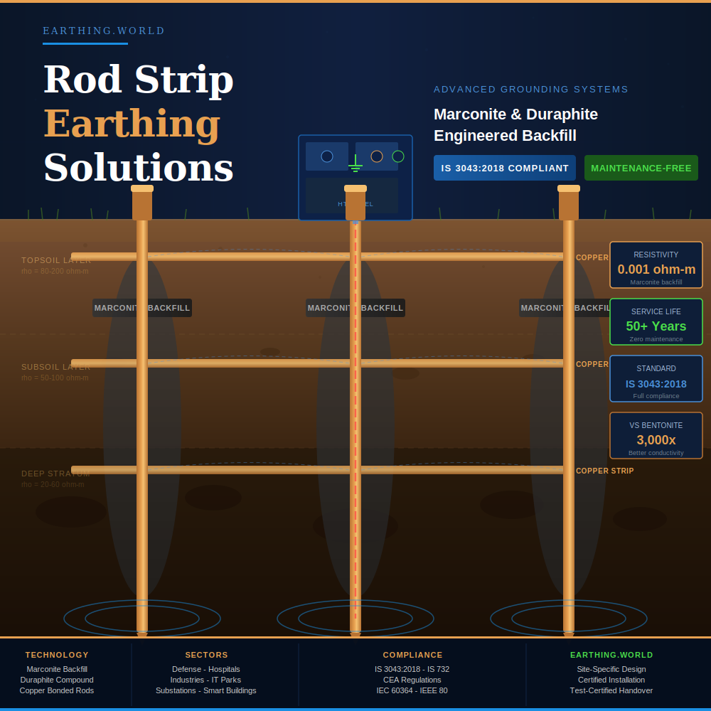
At Earthing.World, we design and install rod strip earthing solutions engineered to achieve ultra-low earth resistance from day one and maintain it, without maintenance, for decades. By combining high-quality copper and GI earth electrodes with Marconite and Duraphite — the world’s most advanced engineered backfill compounds — we deliver grounding systems that outperform conventional installations across every measurable parameter.

Every system we install is designed to full compliance with IS 3043:2018, IS 732, and Central Electricity Authority (CEA) regulations.

What Is Rod Strip Earthing? — The Foundation of Electrical Safety

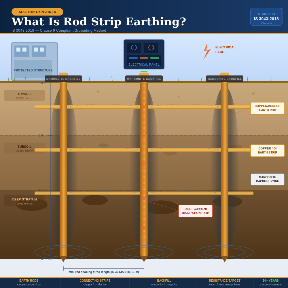
Rod strip earthing is one of the most reliable and widely adopted grounding methods prescribed under IS 3043:2018. The system works by driving copper-bonded or galvanized iron (GI) earth rods vertically into the soil at calculated spacing, then interconnecting them with horizontal copper or GI strip conductors to form a continuous, low-impedance fault current network.

This interconnected electrode grid ensures that fault currents — whether from equipment failure, lightning strike, or insulation breakdown — find an immediate, low-resistance path to earth, triggering protective devices before harm can occur to personnel or infrastructure.

Testimonial

What People Saying About Our Services

Submit Enquiry

Book an Appointment

Review an accurate quote within 3-5 days when you fill out the form on this page. Or, give us a call: (+91 72900 43400)

    IS 3043:2018 Compliance — Earthing Standards We Meet

    Every Earthing.World rod strip earthing installation is designed to comply with IS 3043:2018 (Code of Practice for Earthing — Second Revision), the Bureau of Indian Standards’ definitive standard for earthing system design, installation, testing, and maintenance.

    Key IS 3043:2018 clauses our designs address:

    • Clause 9 — Earth electrode selection (rod, strip, plate types) and sizing per soil resistivity data
    • Clause 10 — Design of earthing systems to control touch voltage and step voltage within safe limits for personnel
    • Clause 12 — Equipment earthing requirements and connection methods
    • Clause 14 & Table 8 — Earthing conductor cross-section sizing per fault current and disconnection time
    • Clause 17 — Thermal withstand capacity of earthing conductors
    • Clause 27 — Inspection access, testing provisions, and maintenance recommendations
    • Clause 40–42 — Earth resistance testing methods, including Wenner four-pin soil resistivity measurement and fall-of-potential earth resistance testing

    We also comply with IS 732 (Electrical Wiring Installations) and applicable CEA Regulations for HT/LT installations. Full compliance documentation — including as-built drawings and calibrated test certificates — is provided at project completion.

    Earthing.World

    Why Standard Earthing Fails — And How Engineered Backfill Solves It

    Conventional earthing installations use salt and charcoal as backfill around the earth electrode. This approach has a fundamental weakness: it depends entirely on soil moisture to conduct. In dry conditions — peak summer, rocky terrain, or sandy substrates — salt-charcoal backfill dries out, resistivity spikes, and the earthing system that passed its commissioning test quietly stops performing to specification.
    The consequences are invisible until a fault occurs. Then they are catastrophic.

    The real-world problems with conventional backfill:


    Salt corrodes the copper or GI electrode over time, progressively increasing resistance. It leaches into surrounding soil and groundwater. It requires periodic replenishment — every 1–3 years — or earth resistance climbs above safe levels. Annual maintenance testing is mandatory precisely because the system is unreliable by design.
    Marconite and Duraphite eliminate all of these failure modes — permanently.
    We do not install generic earthing systems. Every project follows a rigorous, data-driven process from site survey to commissioning — because an earthing system that looks correct but isn't tested is not an earthing system, it is a liability.

    Our 6-Step Rod Strip Earthing Installation Process

    Step 1
    Soil Resistivity Testing We conduct soil resistivity measurement using the Wenner four-pin method (as specified in IS 3043:2018, Clause 40) at multiple locations and depths across your site. This data, not assumptions, drives every design decision that follows.
    Step 2
    Customized Earthing System Design Our engineers calculate rod length, inter-electrode spacing (minimum rod separation per IS 3043:2018, Clause 9 to avoid mutual interference), strip routing, number of earthing pits, and backfill compound selection. We model touch voltage and step voltage to confirm IS 3043:2018, Clause 10 compliance before a single rod is driven.
    Step 3
    Material Procurement & Pre-Installation Quality Check All rods, strips, and backfill compounds are sourced from verified suppliers. We verify Marconite authenticity (genuine Marconite manufactured by James Durrans & Sons Ltd., UK) before use. GI and copper electrodes are checked for dimensional compliance with IS 3043:2018.
    Step 4
    Professional Installation by Trained Earthing Engineers Rods are driven or placed in boreholes to specified depths. Strips are laid and connected using approved bonding methods. Marconite or Duraphite is mixed in the correct ratio (3 parts Marconite : 1 part OPC cement by weight, with 1 litre water per 4 kg total mix) and poured into earthing pits or boreholes.
    Step 5
    Earth Resistance Testing & Verification Post-installation testing using a calibrated four-terminal earth tester (fall-of-potential method). The system is commissioning-certified only after achieving the specified earth resistance values. Individual electrode resistance and combined grid resistance are both recorded.

    Step 6 — Documentation, Compliance Certificate & Handover You receive: as-built layout drawings, calibrated earth resistance test reports, IS 3043:2018 compliance certificate, material authentication certificates for Marconite/Duraphite, and a project completion report. Ongoing earthing audit services are available as a follow-on engagement.

    Earthing.World

    Where Duraphite Outperforms Other Backfill Compounds

    Duraphite is particularly specified for:


    Arid and semi-arid geographies — Sites in Rajasthan, Gujarat, interior Maharashtra, and similar regions where soil dries to very high resistivity values during summer months. Highly weathered or laterite soils — Red soils with low clay content that drain rapidly and fail to retain moisture around conventional backfill materials.

    Sites where borehole drilling is cost-restricted — Duraphite's soil-conditioning properties allow effective earthing in shallower installations where Marconite would require deeper borehole placement.

    Long-term industrial installations — Where a highly stable, graphite-based conductivity matrix is preferred for guaranteed multi-decade performance with zero maintenance interventions.

    How a Rod Strip Earthing System Works

    The physics is straightforward: current always flows along the path of least resistance. A correctly designed rod strip earthing system creates that path deliberately — from the protected equipment, through the earth conductor, into the electrode network, and safely dissipated into the surrounding soil.

    The effectiveness of this dissipation depends directly on:

    1. Electrode contact area — longer rods and denser strip networks increase the surface area in contact with soil, reducing resistance.
    2. Soil resistivity — lower soil resistivity means faster, more complete fault current dissipation. This is where backfill compound selection becomes critical.
    3. Inter-electrode spacing — rods spaced too close create mutual interference; our designs are calculated to minimize this effect per IS 3043:2018, Clause 9.
    4. Conductor sizing — strip cross-sections are sized to carry maximum fault current without thermal damage, per IS 3043:2018 requirements.
    5. Materials Used — Copper Rods, GI Strips & Earth Electrodes

    We use IS-compliant materials selected for the specific site environment:

    Earth Rods: Copper-bonded steel rods (copper cladding as per IS 3043) or solid GI rods, available from 1.5 m to 3 m+ in length. Rod diameter selection follows IS 3043:2018, Clause 9.2 requirements.

    Earthing Strips: Copper flat strips or GI strips, sized per fault current calculations. Copper strips are preferred for high-corrosion environments; GI strips offer a cost-effective solution for standard installations.

    Backfill Compounds: Marconite or Duraphite engineered conductive aggregates — never salt or charcoal, which degrade and require frequent replenishment.

    Earthing Pits & Covers: Pre-cast concrete pit covers with inspection access, ensuring testability per IS 3043:2018, Clause 27.

    Duraphite Earthing — Long-Term Conductivity in Challenging Soils

    Duraphite is a graphite-based engineered backfill compound developed specifically for earthing applications in sites with high seasonal soil resistivity variation — environments where extreme summer dryness or mineral-poor soils make consistent earthing performance difficult to sustain.

    Where Marconite replaces the soil contact matrix with a manufactured conductive solid, Duraphite works by chemically and physically stabilizing the soil resistivity in the electrode contact zone, ensuring the earthing system’s performance remains consistent across the full range of seasonal soil moisture conditions.

    Frequently Asked Questions (FAQs) – Road Strip Earthing Solutions in India

    What is rod strip earthing and how does it work?

    Rod strip earthing is a grounding method where copper or GI rods are driven into soil and interconnected by copper or GI strips to form a low-impedance fault current network. The interconnected electrode grid dissipates fault currents, lightning surges, and leakage currents safely into the earth, protecting personnel and equipment.

    What earth resistance value does IS 3043:2018 require?

    IS 3043:2018 does not prescribe a single universal earth resistance value. Safety is evaluated against touch voltage, step voltage, and fault-loop impedance (Zs) criteria. Commonly applied benchmarks: 0.5 Ω for power stations, 1 Ω for EHT substations, 2 Ω for 33 kV substations, and 5 Ω for distribution transformers.

    Is Marconite earthing truly maintenance-free?

    Yes. Marconite is a chemically inert synthetic aggregate that forms a permanent conductive solid around the electrode. It does not dry out, shrink, wash away, or corrode electrodes. Once installed correctly, a Marconite earthing system requires no maintenance for 50+ years.

    Can rod strip earthing with Marconite work in rocky or high-resistivity soil?

    Yes — this is precisely where Marconite performs best. Its intrinsic resistivity of 0.001 Ω·m compensates for high-resistivity native soil, making it the preferred solution for rocky terrain, sandy substrate, and geographies where conventional earthing methods consistently fail to achieve target resistance values.

    What is the difference between Marconite and Duraphite?

    Marconite is a synthetic carbonaceous aggregate (0.001 Ω·m) that forms a permanent conductive concrete structure — the primary choice for most installations. Duraphite is a graphite-based compound that conditions and stabilizes soil conductivity in sites with extreme seasonal moisture variation. Our engineers specify the correct compound based on your site's measured soil resistivity data.

    What is soil resistivity testing and why is it necessary before installation?

    Soil resistivity (measured using the Wenner four-pin method per IS 3043:2018, Clause 40) quantifies how strongly the soil resists current flow at different depths. This data is essential for correctly sizing the earthing system — without it, the design is guesswork and there is no guarantee the installed system will meet IS 3043:2018 requirements.

    Do you provide IS 3043:2018 compliance documentation?

    Yes. Every project includes as-built drawings, calibrated earth resistance test reports, material certificates (including Marconite authentication), and an IS 3043:2018 compliance certificate.

    Industries & Applications We Serve

    Our rod strip earthing systems with Marconite and Duraphite backfill are deployed across sectors where electrical safety failures have zero tolerance.

    Defense & Government Installations — Mission-critical infrastructure that must perform under all operating conditions, 24/7/365. Our earthing systems are designed to military-grade reliability standards.

    Hospitals & Healthcare Facilities — Medical-grade earthing for ICUs, operating theaters, MRI suites, and life-support systems. Ultra-low earth resistance prevents equipment malfunction and protects patients from micro-shock hazards.

    Industrial Plants & Heavy Manufacturing — Motor control centers, high-voltage switchgear, production line equipment, and substation earthing for steel plants, cement factories, chemical plants, and process industries.

    Power Substations & Utilities — Substation perimeter earthing using Marconite borehole installations to contain fault currents within defined boundaries and meet touch/step voltage limits per IS 3043:2018, Clause 10.

    Data Centers & IT Parks — Precision earthing for server rooms, UPS systems, and sensitive electronic infrastructure. Our systems eliminate ground loops, prevent voltage differentials, and protect equipment from surge-induced failure.

    Telecom Towers & Base Stations — Single-point earthing systems that minimize induced interference and protect tower equipment from lightning discharge.

    Solar Power Plants — DC and AC side earthing for utility-scale and rooftop solar installations, compliant with IS 3043:2018 and CEA Solar Regulations.

    Smart Buildings & Commercial Complexes — Integrated earthing systems for BMS, fire alarm, CCTV, data, and power earthing in high-rise commercial and residential developments.

    Rod Strip Earthing vs Other Earthing Methods — At a Glance

    Parameter

    Rod Strip Earthing + Marconite/Duraphite

    Pipe Earthing (Salt-Charcoal)

    Plate Earthing (Conventional)

    Chemical Earthing

    Initial cost

    Medium–High

    Low

    Low

    Medium

    Maintenance required

    None

    Annual

    Annual

    Annual

    Lifespan

    50+ years

    5–10 years

    5–10 years

    10–15 years

    Performance in dry soil

    Excellent

    Poor

    Poor

    Fair

    Corrosion to electrode

    None

    High

    High

    Low–Medium

    IS 3043:2018 compliant

    Yes

    Yes

    Yes

    Yes

    Lifecycle cost

    Lowest

    Highest

    Highest

    Medium

    Rocky/high-resistivity soil

    Excellent

    Poor

    Very Poor

    Fair

    Commissioning test pass rate

    Very High

    Variable

    Variable

    High

    Benefits of Rod Strip Earthing with Marconite / Duraphite Backfill

    The combination of a correctly designed rod strip earthing network with engineered backfill delivers performance that conventional earthing simply cannot match.

    • Ultra-low earth resistance from day one — Fault current dissipation begins the moment commissioning testing confirms target resistance values. No waiting, no breaking-in period, no hope that the soil stays wet enough.
    • Permanent, zero-maintenance installation — Salt-charcoal systems demand testing and replenishment every 1–3 years. Marconite and Duraphite systems require no maintenance for 50+ years. The labour, testing, and material cost savings over the system lifetime dwarf the higher initial material outlay.
    • Electrode protection from corrosion — Both Marconite and Duraphite are chemically inert and non-corrosive to copper and steel. Your electrodes last as long as your building.
    • Full IS 3043:2018 compliance — Our designs meet touch voltage, step voltage, fault-loop impedance (Zs), and earth potential rise (EPR) criteria as specified in IS 3043:2018 Clauses 3, 10, and 27.
    • Performance in any soil condition — Rocky substrates, sandy soils, high-resistivity ground, extreme seasonal variation — engineered backfills compensate where native soil cannot.
    • Documented ROI over lifecycle — Engineering studies consistently show that Marconite earthing has the lowest total lifecycle cost of any earthing method when installation, maintenance, re-testing, and electrode replacement cycles are accounted for over a 25–50 year horizon.

    Get a Free Earthing Consultation from Earthing World

    Don’t gamble with electrical safety. Speak to Earthing World’s certified earthing experts today for a free site assessment and a customised chemical earthing solution that meets Indian safety standards.

    📞 Call Now | 📧 Request a Quote | 🌐 Visit www.earthingworld.com

    Earthing World – India’s Trusted Partner in Electrical Safety & Earthing Solutions.

    Marconite Earthing — The World’s Most Reliable Conductive Backfill

    Marconite is a premium synthetic conductive aggregate, manufactured by James Durrans & Sons Ltd., UK, specifically for electrical earthing applications. It has been the benchmark material for high-performance earthing installations globally for over 40 years, specified by engineers in substations, defense installations, hospitals, and data centers across 60+ countries.

    When used as backfill around a rod strip earthing electrode, Marconite dramatically increases the effective surface area of the electrode in contact with the surrounding soil — multiplying the dissipation zone without requiring additional rods.

    Key Properties of Marconite (0.001 Ω·m Resistivity)

    Property

    Marconite

    Bentonite

    Salt-Charcoal

    Resistivity

    0.001 Ω·m

    3 Ω·m

    Variable (moisture-dependent)

    Maintenance required

    None

    Yes (watering)

    Yes (annual replenishment)

    Corrosion to electrodes

    None — chemically inert

    Minimal

    High (salt corrosion)

    Performance in dry soil

    Unaffected

    Severely degraded

    Severely degraded

    Service life

    50+ years

    10–15 years

    3–7 years

    Environmental impact

    Eco-safe, no leaching

    Minimal

    Soil/groundwater contamination

    Compressive strength

    > M25 grade concrete

    Low

    Negligible

    pH

    Neutral

    Alkaline

    Varies

    Additional Marconite performance advantages:

    Marconite does not shrink, crack, or wash away. It sets as a solid, high-strength conductive structure around the electrode that remains mechanically and electrically stable regardless of seasonal soil moisture variation. It is non-corrosive to both copper and steel, does not attack cement, and does not alter groundwater chemistry.

    • Its ultra-low intrinsic resistivity — 0.001 Ω·m, compared to Bentonite’s 3 Ω·m (a 3,000× advantage) — means the earthing system achieves its target resistance value at commissioning and maintains it permanently, without a single maintenance intervention.
    • Marconite vs Bentonite vs Chemical Earthing — Full Comparison
    • Marconite vs Bentonite: Bentonite is a naturally occurring clay that reduces soil resistivity by retaining moisture around the electrode. While effective when wet, it fails entirely in dry conditions — which are precisely the conditions when high-load equipment is most active. Marconite requires no moisture to conduct; its electrical properties are intrinsic to the material itself.
    • Marconite vs Chemical Earthing: Chemical earthing compounds (graphite, activated carbon, GEM compounds) are partially effective and superior to salt-charcoal, but none match Marconite’s resistivity (0.001 Ω·m), permanence, or corrosion-free performance. Chemical compounds still rely on periodic soil moisture and are subject to long-term degradation.
    • Marconite vs Conventional Earthing: A conventional rod earthing pit (salt-charcoal backfill) may achieve its target resistance at commissioning but will require retesting and maintenance within 12–18 months in most Indian soil conditions. A Marconite rod strip system achieves and permanently holds target values — with no ongoing cost.